|
76NEWS on 2014-02-25 04:23:29Project Endedby marina |
|
|
|
|
|
Welcome !
|
  
|
You are visitor no. 220354 since 10/14/2010 Visitors Online: 1 Members Online: 0
Page updated:
|
@NLINE APPLICATIONS.::.GEOMODELS.::.SlabDETACHMENT
Cyberinfrastructure for Geodynamic Studies Related to the Vrancea Seismogenic Zone
Slab Detachment - slab detachment due to subduction termination
Model setup and boundary conditions for 4D slab detachment model.
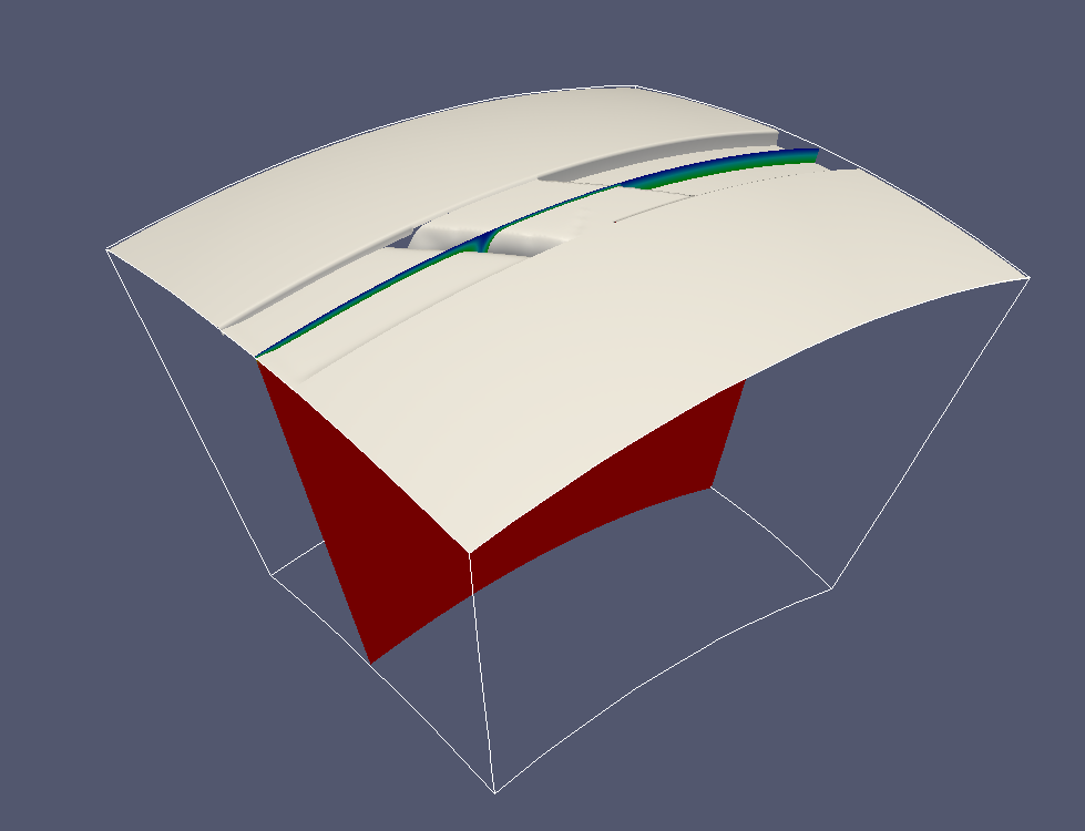
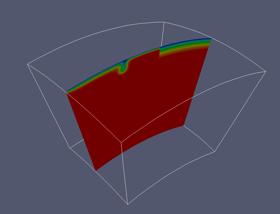
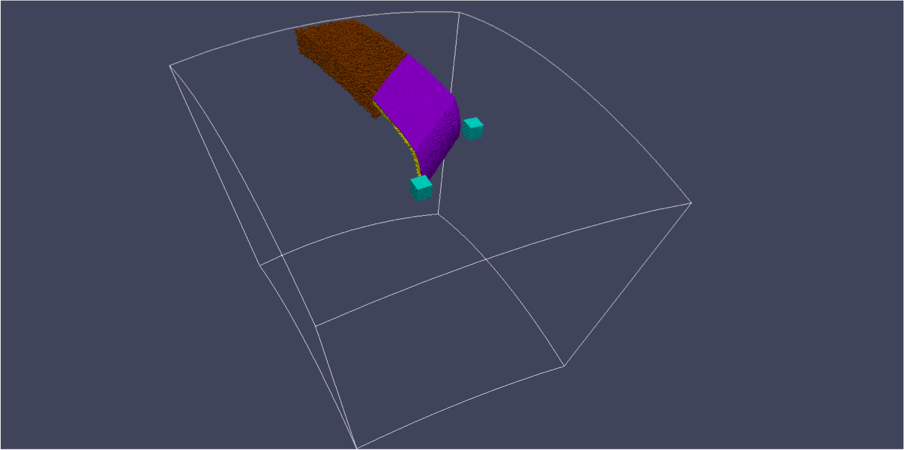
Using the finite element package CitcomS.py Version 3.0.1 (Tan et al., 2006) available from the Computational Infrastructure for Geodynamics (CIG) (http://geodynamics.org), the computations are performed within a 3D spherical domain (θ, φ, r), where θ is latitude, φ is longitude and r is radius (Fig. 1). The inner radius corresponds to a depth of 1900 km, the outer radius the surface of the Earth. The span in latitude and longitude is 23° and 28°. This domain is evenly divided into 129 elements in the radial dimension and 150 x 257 elements in areal (i.e., latitude and longitude) dimension, corresponding to a 15 x 17 x 12 km resolution. The boundary conditions are as follows. The top boundary has an imposed velocity boundary condition corresponding to the movement of the tectonic plates in the Panonian region since 30 Ma. The small oceanic plate subducts at 1.5 cm/yr, and the overriding plate at the same rate. The top and bottom boundaries are assumed to be isothermal. The bottom is free slip, and the sides are reflecting. The initial thermal structure is described by a multiple age thermal boundary layer (see. Fig. 1) with old lithosphere as a 200 Myr old plate and young lithosphere as 10 Myr old.This background mantle is divided into four layers: lithosphere (variable thickness), upper mantle (variable thickness), transition zone (410 - 670 km) and part of lower mantle (670 - 1300 km). The lithosphere has a variable thickness, ranging from 100 km for young lithosphere to 100 - 200 km for the oldest region. The slab surface is modeled using particle tracers (see purple particles in the figures). Tracers' velocities are calculated by interpolating the eight nodal velocities with bilinear shape functions. Tracers are advected using the mid-point method (2nd order accuracy).
|
Initial SETUP
|
 |
|
 |
|
 |
|
|
|
|
|
|
|
|


